Disclaimer

This blog is for entertainment purposes only, and is not meant to teach you how to build anything. The author is not responsible for any accident, injury, or loss that occurs as a result of reading this blog. Read this blog at your own risk.

Friday, May 18, 2018

Ch 22 - Electrical/Avionics - Part 15

George is flying!

I finally got a chance to go out and test fly the servo installation by shooting an actual autopilot coupled RNAV approach, and the results were just amazing.

Check it out…


Letting "George" do some work at last!


I am tempted to say my work here is done, but I know better than that. 

I am however looking forward to more flying and less modifying from now on, and perhaps even getting back to my long term Long EZ project… remember that?! ๐Ÿ˜‰


Sunday, May 06, 2018

Ch 22 - Electrical/Avionics - Part 14

Pitch servo flight test

The one year long upgrade process had come to the end, and it is time to see if this conversion has been a good idea, or a waste of time and money. 

As you might imagine, I couldn’t wait to go flying to check out the fully functional autopilot.

Would it work well?

Would it work at all?

The wait was killing me! Meanwhile 7JT sat quietly in the hangar, perhaps still a little sore from the latest cyborg implant.

Luckily, I wouldn’t have to wait long for a couple of sunny days on which to fly. 

I actually conducted four flights over two days, and aside from a couple of control reversal issues (fun fun) due to software settings I was positive I had changed, the installation only required a little more torque output from the servo (another software setting) before 7JT started to perform the way I knew she was capable of.

“Fanfreakingtastic!”

Unfortunately, due to reasons unrelated to the servo installation, and that were since resolved, I had to fly these flights in heading mode, and I didn’t get to shoot any approaches. I’ll try doing that over the next few flights, however I wanted to show you a few pictures of the pitch servo in action during a couple of descents, one in IAS (Indicated Airspeed) mode, the other in VS (Vertical Speed) mode.

First though, let me show you the only climb shot I’ve got in which the sun didn’t fade the whole scene out… 


Constant 120kts airspeed climb to 6500'

After climbing to 6500’, I made a few turns. Here’s one to the left…

Level turn to a southerly heading

After flying a 15 minutes closed loop in heading mode, I found myself on the way back home, needing to descend. I broke up the descent in multiple sections in order to get a little more practice, and highlight any possible issues.

For the first descent, I selected 5500’ and chose a constant speed of 160kts. The Flight Director immediately commanded a dive, but the autopilot was very smooth in lowering the nose to follow it.


Process of beginning a descent in constant speed mode

As the airspeed reached the selected 160kts, the Flight Director rose to maintain the speed, and the autopilot smoothly followed its command.


Constant speed descent established

Roughly 100’ prior to reaching the selected 5500’, the vertical autopilot went into “Altitude Capture” mode, during which the nose is raised to level the plane off. At this point I added enough power to maintain my normal cruising speed.


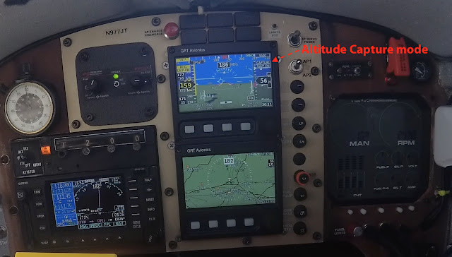
Starting the leveling maneuver

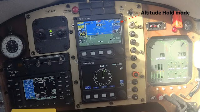
The autopilot then went into “Altitude Hold” mode. The airspeed decayed to whatever the power setting I used would support, and the autopilot pitched to maintain altitude.


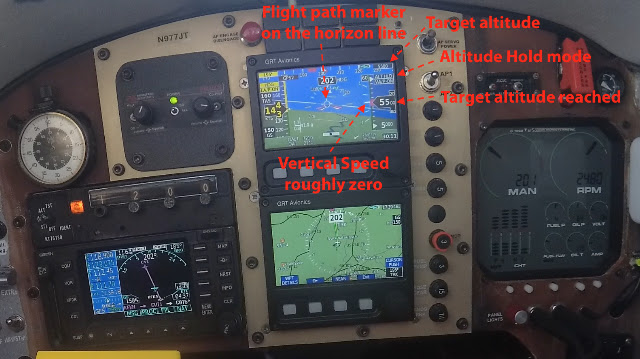
New altitude reached and level off completed

The next descent to 3500’ was started in IAS mode at 180kts, but then I switched to VS mode at -500 fpm (feet per minute) due to turbulence, and also to check that mode.


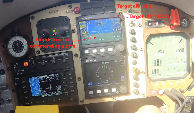
New descent to 3500' selected, with constant airspeed of 180kts.

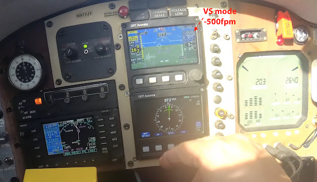
Too bumpy for 180kts, I switched to a constant Vertical Speed descent at -500fpm

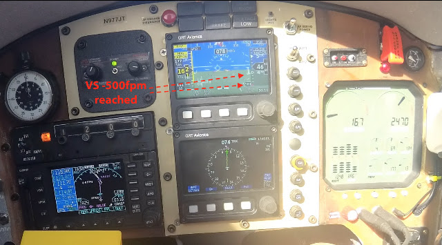
Vertical Speed descent fully established

Once again the autopilot went into “Altitude Capture” first, then the “Altitude Hold”.


Should start to look familiar by now

"That's right... you've got this now!"

What else can I say… I am beyond ecstatic. 

As awesome as 7JT has always been, she has now become the airplane of my dreams. Long trips will now be less stressful, and more fun, and I’ll be able to spend more time looking outside, both for traffic and to enjoy the view. 

Should the occasional cloud get in the way, 7JT is now capable of just about any approach one can think of, precision and non, and do it all by itself, including Missed Approaches and Holdings. 

All it’s required of me now is to stay awake, and enjoy the ride.


I can hardly imagine money and time better spent.


Wednesday, May 02, 2018

Ch 22 - Electrical/Avionics - Part 13

Pitch servo installation


With spring warmth at hand, I decided to get cracking on the pitch servo installation. 

I had a pretty good idea of where the servo should go. I wanted the heavy steel mass as far forward as possible to help with the center of gravity (CG), but I knew this location would require dismantling some of my previous work, and perhaps relocating and rewiring the entire ground bus.

Aside from getting installed in a forward location, the pitch servo would also need to connect to the elevator pushrod. The place I had in mind was right in front of the engine instruments, on the right fuselage sidewall, where a bracket already existed from the vacuum filter days, though it was currently being used by the ARINC module. 


Bracket supporting the vacuum filter (before "steam gages" replacement)

Vacuum bracket liberated during EFIS installation

ARINC module looking for a home

Vacuum bracket repurposed as ARINC support

The area behind the engine instruments is pretty spacious, but more importantly it is right over the top of the elevator control tube.


Looks like the ARINC module might need to find itself a new home

I spent quite some time figuring out how to make this location actually work, but eventually I ran into an unforeseen problem. 

While busy congratulating myself on how smart I had been reusing the existing bracket once again, I noticed that my compass was indicating 60ยบ off its normal reading. Initially confused by it, I tried moving the servo slightly, and the compass just went nuts! 

That’s when it donned on me that the big hunk of steel was rendering the compass useless. I really should have known.

Double “DOH!”


Oh... it looks so obvious now!

So, I tried moving the servo all over the cockpit while observing the compass. Sadly, any place within two feet of the compass adversely affected the compass readings. There was a slight possibility of installing it way up front in the nose, forward of the canard, but the connection to the elevator rod would have been at a terrible angle, and I would have had to really tear this plane apart to do it. Some things are just better done while building the plane rather than afterward.

Never fear though, I had a plan B up my sleeve, although it wasn’t as good as plan A for moving the CG forward...

Because the LongEZ has a rear control stick, I might still be able to connect to the elevator control tube there, perhaps without inconveniencing the passenger too much. The plan was still to place the servo as far forward as possible, which now meant against the front seat, then connect it somehow to the tube in question.

Often a one-man building team, I leveraged velcro power to help me find a new place for the servo, and hold things together while I pondered on the new setup.


Investigating an alternative pitch servo location

After talking it over with my friend Wade, plan B started making a lot of sense, and as a bonus I wouldn’t even need to machine a new connector if I attached the servo rod directly to the rear stick. All I needed was a longer bolt and a few washers.


That just looks made for it

Please forgive the huffing and puffing on the next video, as I was laying with my chest on the left longeron, feet on a step stool, trying to get a good shot for you. 


Checking the feasibility of this location


Having decided on the location of the servo, the multi-day installation process began.

Day one was clickbonds install day…


Location of servo bracket identified

Sidewall sanded

Clickbonds (with flox) bolted to the bracket

Epoxy painted on sidewall

Bracket in place secured with tape

Heat lamps helping the flox cure overnight

Day two was spent fiberglassing over the clickbonds…


Flox cured

Flox sanded smooth, and electric tape ready to protect the threads from the epoxy.

A few plies that will go over the clickbonds

Sidewall prepped

Pre-preg ready

Pre-preg going over the clickbonds

BID pre-preg installed

Peel-ply over fiberglass

Bracket lightly attached to the clickbonds

Day three was sanding, and servo mounting day…


Peel-ply removed, all edges sanded smooth.

Pitch servo solidly attached to the plane

Servo arm attached to the rear control stick

A view of the servo control arm

Day four was spent wiring the servo all the way to the instrument panel backplate (aka junction box)


Using a 90ยบ dsub female to male connector to manage the wiring

Another look at the finished installation

That's it! The autopilot installation is completed. All that's left to do now is go fly, and make sure the autopilot behaves predictably.

I shall let you know how it all went, soon.